

The Kappel Rigging Trainer (KRT) enables more effective and accessible teaching in the classroom and on stage. The frame of the trainer mimics the cross-section of a typical proscenium-style theater with galleries and a walkable grid. The line sets include single and double purchase manual sets, and a traditional hemp set. Common variations of rope locks and counterweight arbors are included. All of the equipment functions like a real system, including rope lock slippage and runaway behavior, allowing for procedures to be demonstrated and practiced safely.

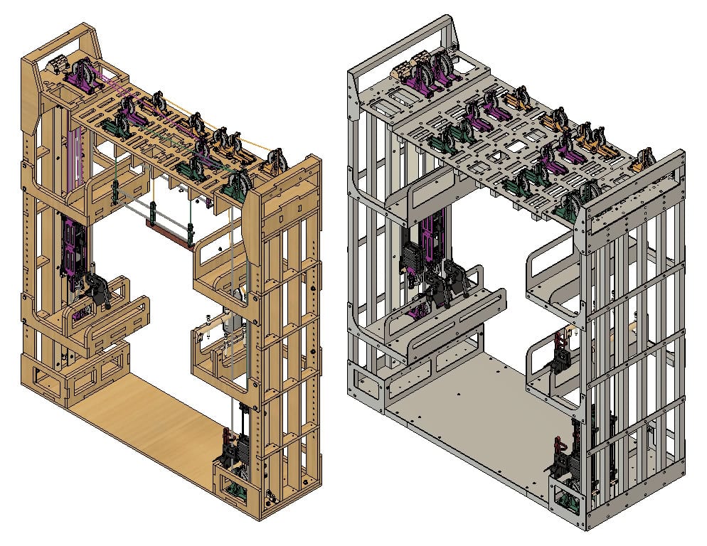
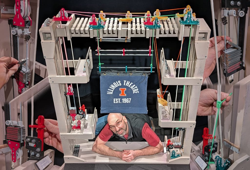
Flat-Pack Frame with Three Line Sets


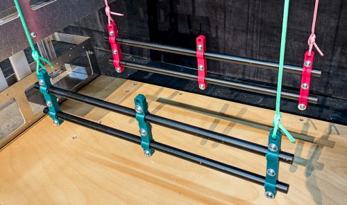
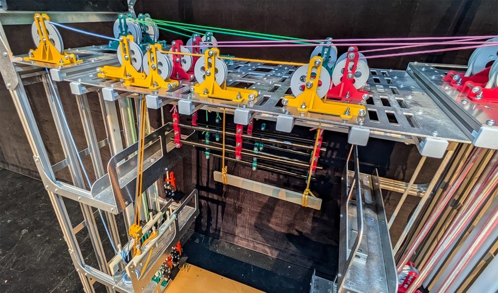
Square-Stock Frame with Five Line Sets


About the KRT
The Kappel Rigging Trainer was created by Matt Grenier and is named in memory of his personal mentor, Martin W. Kappel (1953-2005). Martin was a devoted husband, father, educator, and a thespian to his core. His professional accomplishments were extensive. On May 31, 2005, Martin’s life was cut short by a tragic accident involving a counterweight rigging system. While working at a local school, lighting equipment was removed from a batten before the counterweight was unloaded from the arbor. The resulting arbor-heavy runaway caused Martin to be pulled off the floor by the purchase line.
Sadly, accidents of this type can happen to anyone. Runaways are far too common. Of course, the outcome of a runaway varies depending on the specific conditions. Except in the most severe cases, these accidents are not widely reported. Still, many of us working in the industry have a story, or know someone who has a story, about a counterweight system runaway.
Even with industry efforts to move toward motorized rigging, the reality is that manual counterweight rigging remains prevalent and will be for a very long time. It is therefore incredibly important that effective training be available to students and working technicians. There are problems that inhibit the delivery of such training, the first of which is access to a rigging system. This is why the KRT was created; to improve access and retention of information that helps keep us safe. The KRT was also created to preserve and share Martin’s passionate devotion to arts education and performance.
To learn more about Martin’s legacy and the development of the KRT, read the feature article in the Fall 2025 issue of ESTA’s Protocol magazine.
Narrated by his wife Victoria, the below career retrospective was created for the ceremonial renaming of a theater in Martin’s memory.
Existing Problems
The KRT was developed to address problems that often inhibit the teaching of counterweight rigging. Some of those problems include:
- Qualified educators may not have access to real rigging system(s)
- Students are unable to see all parts of a real rigging system when standing on stage
- Students may have difficulties visualizing how a system works when only looking at pictures or diagrams
- Students may not fully engage with training that is all lecture-based
- Students with accessibility needs may not be able to fully participate in training
- If mistakes are made with a real rigging system, the consequences are high-stakes
How does the KRT address the problems listed above?
- Educators now have a functional rigging system they can use for teaching
- The scale of the trainer allows all parts to be observed at once
- Students can observe the operation of a physical, functional rigging system sitting right in front of them
- Students can engage constructively with the material through hands-on interaction with the rigging system
- Students that cannot physically operate a real rigging system, or ascend to fly floors/weight floors/grids, can effectively do those things with the trainer. Students with visual impairments can physically interact with all the parts of the trainer. Students with color blindness can distinguish between the different color-coded line sets of the trainer. Regarding working with real rigging systems on stage, it is important to emphasize that every person that is well-trained in the parts and procedures can play a critical role in safety oversight for others… even if they are not able to directly work with the rigging system themselves. To take this one step further, rigging educators with accessibility limitations can also use the trainer to deliver effective instruction even if they have difficulties operating or accessing parts of a real rigging system themselves.
- Mistakes are an important part of the learning process; with the trainer, mistakes can be made with very little risk of injury. Problems with comprehension or execution can be more safely identified when students make mistakes on the trainer before making them on a real system.
Design Goals
The creation of a functional, miniature counterweight system for classroom teaching requires seemingly endless factors to be considered. There are many different priorities that can be pursued and trade-offs that can be made. Ultimately, the goals for the KRT were as follows:
- Size the trainer so that it is not too large to store and transport easily in a school or classroom environment
- Scale and colorize the parts so that they can be distinguished from a distance, even by those with color-blindness
- The parts should look like the real parts (a rope lock should look like a real rope lock)
- The parts should be functional so that they will create behavior analogous to a real system (the rope lock should function like a real rope lock)
- The trainer should include single, double, and hemp line sets for comparison and discussion of the evolution of rope line systems
- The ropes in the system should be relatively easy to install, tension, and adjust trim without minimal knot tying
- The trainer should include the most common variations of rope locks and counterweight arbors found around the world
- The trainer should be buildable using readily available materials, hardware, and techniques
- The custom plastic parts should be 3D-printable on a typical FDM printer using minimal to no supports
- The trainer should break down into separate tower and grid assemblies without disconnecting or unreeving the operator purchase lines
- The design should anticipate and accommodate open-source modification by users
- The design should include a supplemental transport cart and an option for integrated overhead lighting
Frame Variations
There are two variations of the structural frame of the KRT: the flat-pack frame and the square-stock frame. Both variations of the frame will be available in three and five line set versions.
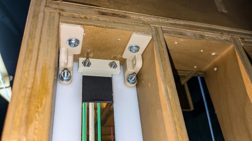
The flat-pack frame utilizes a sheet good, like high-quality plywood. The parts include tab-and-slot features to aid in alignment during assembly. The parts are intended to be cut by a machine, like a CNC router. The three line set prototype is made from 1/2” Grade A birch plywood cut by a router using a 1/4″ bit with some holes and slots made by a 3/16” bit. Drawings will be provided for users that may want to manually cut their parts without using a CNC.
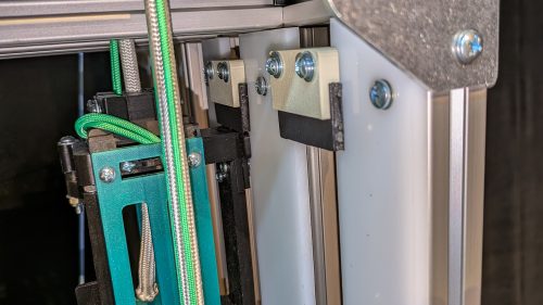
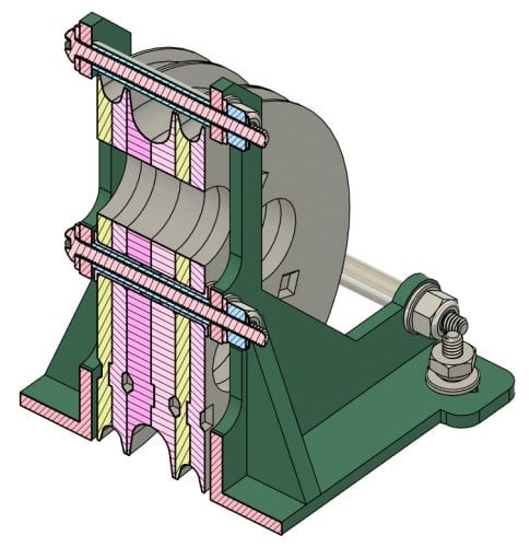
The square-stock frame utilizes stock with a square external cross-section joined by flat plates and gussets. The five line set prototype uses 10 Series 8020 extruded aluminum as the square stock and laser-cut 1/8” aluminum plates. This design can be easily modified by the user for different square stock including steel, aluminum, fiberglass, or even carbon fiber. The plate parts can be cut from different materials with different thicknesses as well.
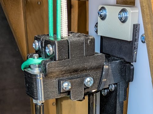
Rope Locks
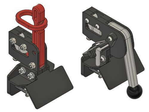
There are many different styles of rope locks. Styles in the United States usually require the handle of the lock to be raised to engage the lock. The handle is most-commonly secured with a ring that captures the rope. Sometimes the handle is secured with a spring-loaded latch that is released by a push-button. Styles of rope lock more common outside of the United States require the handle to be lowered to engage the lock. Locks of this style may or may not have a secondary latch to secure the handle. Additionally, rope locks may use different means of holding the rope. Some rope locks function by pressing two cams tightly against the rope, others by pushing a tight bend into the rope.
For the KRT, it was not possible to accurately accommodate every variation of rope lock that exists. However, it was a priority to represent the two most common types since they require opposite actions from the operator. These types are referred to by their handle operation as “RTL” (raise to lock) and “RTU” (raise to unlock). The RTU version includes a barrel bolt latch.

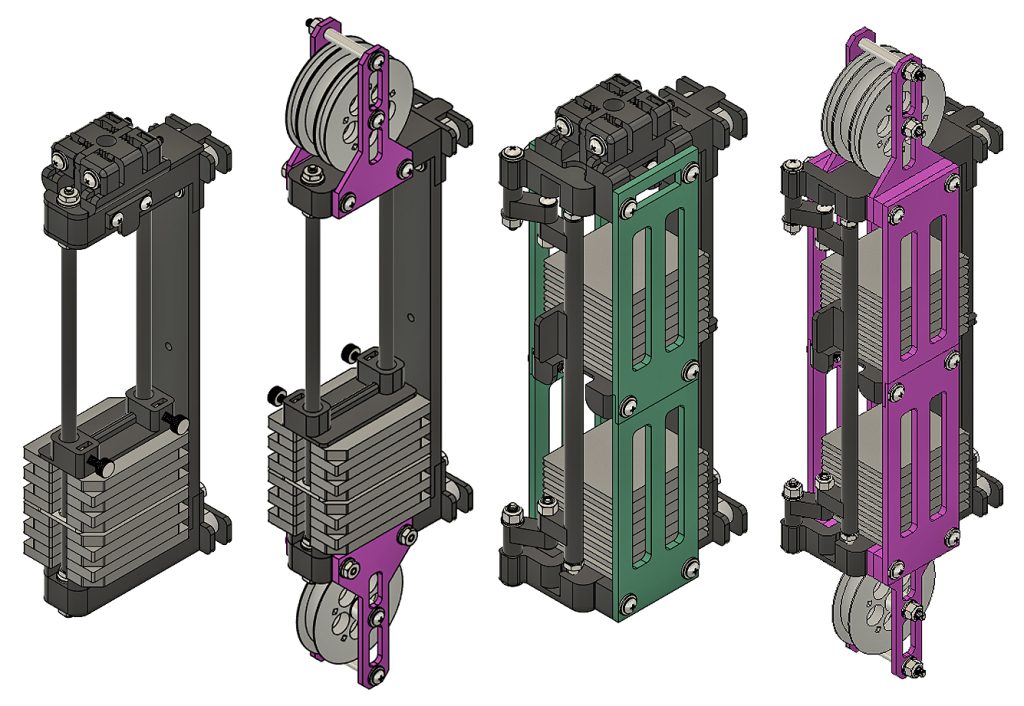
Arbors & Counterweights
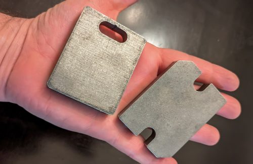
Like rope locks, there are many variations of arbors and counterweights found around the world. The KRT includes two common styles of counterweight arbor: the rod-style and compartment-style. Each are offered in single and double-purchase variations. All versions of the arbors include track guide-shoes that can be easily replaced to accommodate different track openings and thicknesses (without dismantling the entire arbor).
The steel counterweights are offered in versions for each arbor. They are 2” wide and 1/2” thick for “full bricks,” 1/4” thick for “half bricks.” The current prototype bricks were laser-cut by Productions Unlimited. Bricks can also be made manually from flat-bar steel by drilling, cutting, and grinding or sanding.
Guide Track & Crash Bars
The arbor guide tracks are made from strips of 1/4″ HDPE plastic. In the flat-pack prototype, the track is mounted to the plywood using 3D-printed brackets. In the square-stock prototype, the track is mounted directly to the 8020 using T-slot hardware. The arbor stops, or crash bars, are 3D-printed assemblies which clamp onto the guide track and serve as holders for a sacrificial piece of 1/4″ foam core board.
Sheaves & Blocks
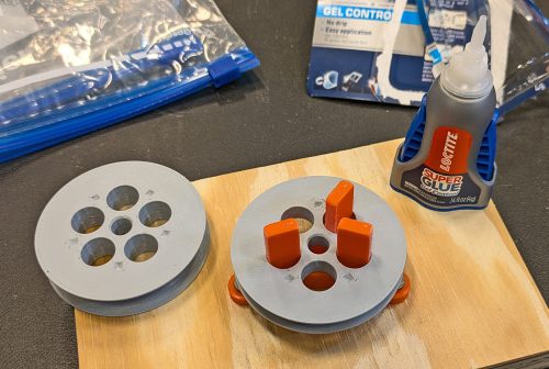
The KRT pulley sheaves include two different sizes identified as “small” and “large.” Each sheave size is provided in two different groove versions: a 3/16” groove for the small lift line ropes and a 3/8” groove for the larger purchase line rope. The small sheaves are used for the loft blocks and double-purchase arbors. The large sheaves are used for the head and floor blocks. To ease manufacturing, each sheave is designed to be 3D-printed in self-aligning halves which are then glued together. To assemble stacks of sheaves, a 3D-printed indexing tool is used to align the sheaves with one another.
The sheave bearings are an ongoing challenge in the KRT design. Ensuring users can source axles and bearings is a concern. Tolerancing and concentricity issues during assembly is also a concern. In the first prototype, the 3D-printed sheaves sat directly on nylon spacers. This worked okay for the loft blocks but there was a lot of friction in the head and floor blocks. The current sheaves utilize igus iglide dry flange bearings riding on nylon or aluminum spacers. Ball bearings have also been explored and may be revisited.
Battens
The KRT battens are a ladder style made from 1/2″ steel rod and 3D-printed brackets. This is necessary to ensure the batten is heavy enough to require pipe weight on the arbor (the empty arbors cannot be heavier than the battens).
Ropes
The lift lines are typical 550 Paracord and the purchase lines are 1/4″ or 5/16″ Para-Max parachute cord. The sheaves and arbors are designed to accommodate lift lines up to 1/8″ in diameter and purchase lines up to 3/8″ in diameter. In practice, it may be best not to exceed 5/16″ for the purchase lines.
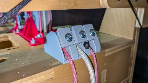
Attaching the ropes to the structural frame, arbors, and battens is achieved through a combination of knot-tying and clamping the ropes into custom 3D-printed parts. For the single-purchase arbors, the purchase line is tied to the bottom of the arbor in a traditional manner. It is then reeved through a screw-operated clamp in the top of the arbor which allows for easy tensioning. The lift lines are also anchored in screw-operated clamps which allows for easy trimming (leveling). This is similar for the double-purchase line sets, except the clamps are mounted to the top of the structural frame rather than integrated into the arbor.
Hemp Rigging
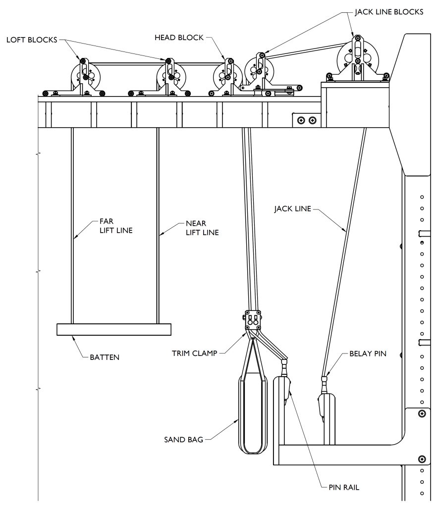
The hemp line set of the KRT includes a batten from flat bar steel, two lift lines, a trim clamp, a sandbag, a jack line, and two pin rails with removeable belay pins. A hemp line set is included in the KRT for a few reasons. First, modern counterweight systems are closely related to historical hemp systems. The systems have parts with common functions. Both leverage the same fundamental principles of physics. Understanding the history of theatrical rope line systems provides context for why they look and function the way that they do.
Second, because hemp rigging has fewer specialty parts and mechanisms, it can be used to deliver a lesson which progresses from a single rope and pulley to the need for tying off the rope, to a multi-line system, to the need for counterweight, to the logistics of safely changing the weight balance, etc. All of these fundamentals can be introduced through the hemp line set before moving on to the modern counterweight systems.
Lastly, hemp rigging is still used. Though it is rare to see full-stage hemp systems in the United States, it is more common elsewhere around the world. Also, hemp rigging techniques are still used for special or temporary rigging applications alongside other modern rigging systems.
How and when can I get a KRT for my school/classroom?
The KRT documentation will be released for free in summer 2026 under a Creative Commons BY-SA 4.0 license requiring attribution and permitting commercialization. Anyone in the world will be free to build their own KRT. Independent contractors and businesses will be free to offer parts or build services to clients seeking a KRT. Educators will be encouraged to deploy their own KRT and share their findings and improvements with others.
See the section titled “Future Plans” for further details. You can also request information and sign-up for updates through this Google Form.
How is Productions Unlimited involved in the project?
Productions Unlimited is supportive of the KRT mission and has plans to help people build their own trainers by offering kits of parts for sale once the open-source project materials are released to the public. As of March 2026, Productions Unlimited has supported the project by donating custom manufactured parts and offering booth space at USITT. For the prototype trainers on display at USITT, Productions Unlimited donated all of the laser cut steel and aluminum parts comprising the square-stock frame, the counterweights, and the batten loads.
How must does it cost?
There are many factors that could affect the total cost to build a trainer from scratch. Are you doing the work entirely yourself and only purchasing materials? Are you hiring a CNC shop to cut parts for you? Are you ordering 3D-printed parts from a print service or printing them yourself? Are you ordering a kit of parts from a vendor like Productions Unlimited? Are you hiring the entire build out to someone else? The answers to these questions drastically alter the price tag.
The first prototype ever built had a budget of around $1,000 in materials. The current three line set flat-pack trainer could be built for a similar material cost. The five line set square-stock trainer would be considerably more expensive given the custom laser-cut sheet metal and extruded aluminum parts. For the prototype, the 8020 stock and hardware alone was around $1200.
How big is the trainer?
The three line set trainer is 4 feet wide, by 4-1/2 feet tall, by 1 foot deep. The five line set trainer is the same width/height and about 18 inches deep.
What is the scale?
The trainer does not conform to a scale. The relative size of components is not realistic by design. Rather, the components are sized to optimize visibility and interactivity given the overall form-factor of the trainer.
Does it function like a real system?
YES! The trainer functions with behavior that is analogous to a real system. For example, the rope lock cam tension can be adjusted to ensure that the line set will slip and runaway if the set is loaded incorrectly or not secured with a snub knot, axe handle, or Uncle Buddy.
How were the 3D-printable parts designed and printed?
The parts were designed using Autodesk Fusion and printed mostly on a Prusa i3 MK3S+ FDM printer. Some parts were also printed on Creality K1 or K2 FDM printers. The first prototype parts were printed using PETG filament while the final parts were printed using PLA. All parts were printed using the standard 0.4mm nozzle. Most parts were printed with 2-3 shells and 15-20% rectilinear infill. Parts were printed at different layer thicknesses and speeds to reduce overall printing time. Very few parts required support material. Some small parts required brims or skirts to ensure bed adhesion.
Why are the line sets color-coded green, magenta, and gold?
These colors can be differentiated from one another with most common types of color blindness.
What hardware is used throughout the trainer?
The custom parts are assembled using #8 machine screws. Many of the parts are designed with cutouts to accept #8 hex nuts. The arbor rods are made from #10 threaded rod. The pulley block side plates are spaced apart using nylon or aluminum spacers for #8 machine screws. The flat-pack trainer frame was assembled using wood glue, brads, and 1/4″-20 bolts. The square-stock trainer frame was assembled using #10 machine screws and T-slot hardware.
What are the sheave bearings?
The current prototypes use igus iglide dry flange bearings riding on nylon or aluminum spacers.
How much weight can you load onto the batten or arbor?
A weight capacity or limitation has not been determined. The arbor capacity is limited by the size of the counterweights and height of the arbor. It has been found that approximately 5lbs needs to be placed on the single purchase batten to counteract frictional losses and achieve realistic behavior. The counterweight required to balance the batten load is not truly one to one due to frictional losses.
What software was used to design the KRT?
The KRT is modeled in Autodesk Fusion using a top-down skeleton of sketches referencing external variables. This allows the frame structure and other parts to be recalculated easily. For example, the flat-pack frame can be recalculated for a different material thickness and router bit diameter by changing only two variables. CNC layouts are created using the Arrange tool available in the Manufacturing Extension.
The development of the KRT has included demonstrations and formal classroom teaching. Below are some findings:
- Material can be covered efficiently and interactively
- The teacher can stand behind the trainer and be seen through it (depending on what is being flown on the battens)
- With sufficient load on the batten, the behavior of the trainer is analogous to a real system; i.e. the line set will slip and run if it is not secured with a snub line, axe handle, or Uncle Buddy
- Tailored supplemental lecture material is desirable to draw parallels to real world systems (including close-up photos of the trainer parts)
- Classroom setup can be tricky depending on the room, number of students, location of the screen/projector, height of trainer, etc
- Extra 3D-printed assemblies and/or examples of real hardware are useful to pass around the room for closer inspection by students
- There is ample promise for varied teaching methods (direct and constructivist), and exploration of advanced rigging topics

A timeline of project development:
- 3/19/26 – Display and demonstration at Productions Unlimited booth #525 at USITT 2026 in Long Beach, CA
- 3/8/26 – Sewed new curtains and sandbags
- 3/7/26 – Prepared informational placards for USITT
- 3/3/26 – New prototype trainers freight shipped to USITT
- 3/2/26 – Completed assembly of new prototype trainers and took photos for documentation and promotion
- 2/28/26 – Assembly and installation of rope locks and arbors onto trainer frames
- 2/24/26 – Assembly and installation of pulley blocks onto trainer frames
- 2/16/26 – Received parts from Productions Unlimited for new batten loads (lighting fixtures and scenery)
- 2/16/26 – Assembly of aluminum parts for square stock frame
- 2/15/26 – Assembly of plywood parts for flat-pack frame
- 2/14/26 – Began build of the next full trainer prototypes (cutting plywood and 8020 aluminum to build frames)
- 1/30/26 – Began design of USITT booth display
- 12/22/25 – Began 3D-Printing components for next full trainer prototypes
- 12/9/25 – Visited Productions Unlimited in-person and picked up custom steel and aluminum parts
- 11/18/25 – Began collaboration with Productions Unlimited to manufacture custom parts and bring new prototypes of the trainer back to USITT
- 11/12/25 – Resumed design and documentation work to prepare for next full trainer prototype building
- 10/1/25 – Feature article published in ESTA’s Protocol magazine titled “Introducing the Kappel Rigging Trainer: How a tragedy formed Martin’s legacy.”
- 9/24/25 – Waterjet cut new prototype counterweight from 1/4″ steel
- 9/13/25 – Began design of a metal variation of the frame made from square stock and custom sheet metal parts
- 9/12/25 – Registration of domain kappelriggingtrainer.com
- 6/30/25-7/30/25 – Extensive redesign and prototyping including reworked sheave bearings, a new European-style rope lock, compartment-style arbors, and variations of the frame made from tab-and-slot CNC-cut parts
- 4/8/25 – Promotion of trainer at University of Illinois’ Research Live! speech competition
- 3/31/25 – Use of trainer prototype to teach counterweight rigging in Intro to Stage Rigging class
- 3/6/25 – Display and demonstration at USITT 2025 in Columbus, OH
- 2/19/25 – Use of trainer prototype to teach hemp rigging in Intro to Stage Rigging class
- 2/16/25 – Launch of webpage on MattGrenier.com
- 2/6/25 – Mock-up of display stand and lighting for USITT
- 1/17/25 – Photographing prototype for documentation and promotion
- 2/6/25 – USITT Poster session final-draft slides
- 1/10/25 – Demonstration of the trainer at Illinois High School Theatre Festival (IHSTF)
- 1/9/25 – Reassembly of prototype in preparation for Illinois High School Theatre Festival (IHSTF)
- 1/8/25 – Painting and clear-coating
- 1/7/25 – Breakdown of prototype for painting, installed bolts for easier disassembly later
- 1/6/25 – Sewing miniature curtains, including pleated “Velour” curtain with pockets for steel weights
- 1/6/25 – Thumb screws 3D-printed for top arbor spreader plates
- 12/10/24 – USITT Poster session first-draft slides
- 12/8/24 – First prototype trim clamp for hemp line set
- 12/5/24 – Use of trainer prototype to teach introductory lesson to Stagecraft class
- 12/4/24 – First functional tests and development of loads to hang on battens
- 12/4/24 – Installation of 3D-printed parts onto wooden frame
- 12/4/24 – First prototype “Uncle Buddy” 3D-printed
- 12/3/24 – Assembly of “final” parts for prototype (rope locks, pulley blocks, arbors, etc)
- 12/1/24 – First counterweights made
- 11/24/24 – First “final” parts 3D-printed in color PLA
- 11/23/24 – Wooden frame build completed
- 11/20/24 – Finished build drawings and began build of wooden frame
- 10/20/24 – First prototype double-purchase arbor
- 10/15/24 – First prototype sheaves and pulley block
- 10/6/24 – First prototype single-purchase arbor
- 9/29/24 – First custom parts designed, 3D-printed, and assembled (the rope lock)
The KRT will be released for free in summer 2026 under a Creative Commons BY-SA 4.0 license requiring attribution and permitting commercialization. Anyone in the world will be free to build their own KRT. Independent contractors and businesses, like Productions Unlimited, will be free to offer parts or build services to clients seeking a KRT. Educators will be encouraged to deploy their own KRT and share their findings and improvements with others.
If you have an interest in the KRT or would like to submit feedback, please fill out this Google Form.
What will be included?
- Guide to building your own KRT, including assembly instructions and factors to consider before purchasing materials or starting to build
- Parts list and index/guide to KRT part numbering (excluding off-the-shelf hardware, there are over 400 numbered parts/assemblies across all versions)
- Drawings and CNC layouts for all versions of the structural frame (flat-pack frame and square-stock frame, in both three and five line set variations)
- Part and assembly drawings for all 3D-printed elements
- STL Files for all 3D-printed elements (including versions using metric hardware)
- Designs for integrated LED strip lighting for optimal visibility of the trainer
- Designs for a rolling cart on which the trainer can be stored and transported
- Supplemental educational materials and teaching tips
Ideas List
- Further revision of the sheave bearings to improve performance
- Functional “chain hoists” that can be used to demonstrate overhauling a batten
- Functional block and tackle that can be used to overhaul the hemp lines
- Version of the trainer that can be collapsed and packed into an ATA flight case
- Miniature elements needed to teach other rigging concepts like motor/truss, arena rigging, curtain systems, etc
- Workshop/session at USITT!
The Story of the KRT
Read the magazine feature article!
The story of the Kappel Rigging Trainer was featured in the fall 2025 issue of ESTA’s Protocol magazine. The Entertainment Services and Technology Association (ESTA) is a non-profit trade association for the entertainment technology industries.

Watch a three minute explanation of the KRT!
Research Live! is a speech competition hosted by the Graduate College at the University of Illinois Urbana-Champaign. Graduate students have three minutes to explain their research and its impact to non-experts. The development of the Kappel Rigging Trainer was presented in a speech titled “Teaching Theatrical Counterweight Rigging in the Classroom.” This speech was selected as one of 13 finalists and received the “Storyteller Award.” For more information about Research Live!, visit the Graduate College website.

Build Photos


Video Demonstration
Recorded in 2025, this video shows the first prototype of the KRT.
Request Information or Submit Feedback
If you would like to request information or submit feedback about the Kappel Rigging Trainer, please fill out this Google Form.
Alternatively, you can contact Matt directly using the contact form.

First Prototype
Shown below is the first prototype of the KRT, developed during the 24-25 academic year at the University of Illinois Urbana-Champaign. This prototype was built from a combination of commonly available scenic materials, hardware, and custom 3D-printed parts. This trainer served as the proof-of-concept for the current KRT prototypes.


The first prototype of the Kappel Rigging Trainer was featured in a digital poster session at USITT 2025 in Columbus, Ohio. Use the arrows below to navigate the slides. The United States Institute for Theatre Technology (USITT) promotes dialogue, research, and learning among practitioners of theatre design and technology. “Poster sessions” are a means of publishing and sharing research at national conferences. For more information visit USITT.org.


